Instruments and methods (Railway vehicles)
- Roller Rig designed using a modular approach, composed by 4 independent rollers, for the development of dynamic tests on railway vehicles prototypes in reduced scale. It is possible to change the wheelbase (1.8 – 3.5 m in scale 1:5, 1.45-2.8 m in scale 1:4), the gauge and the roller profiles. The bogie can be used to perform parametric tests or optimization tests by varying the vehicle characteristics.
- Modular bogie for the European standard track gauge, which completes the test bench (roller-rig) with the possibility of variating the wheelbase (1.8-3.5 m scaled), the characteristics of the suspensions independently for the three directions, the wheel profiles and the axle load. The test-bench can be used to perform running stability tests, traction/braking simulations, slant tests and comfort analysis.
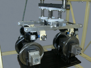
Figure 1: modular bogie (scale 1:5)
- Prototype of narrow gauge bogie (scale 1:4).
- Dartec 9600, hydraulic universal proof machine
- Zwick, electromechanical universal proof machine (static proof).
- Machine for rotating bending fatigue tests.
- Signal analyzer DIFA
- Ultrasound measuring system for non-destructive controls
- Multichannel measuring system for strain-gauges
- Dynamic acquisition system with 96 channels (National Instruments) with integrated signal conditioning for:
- accelerometers/Microphones ICP
- capacitive accelerometers
- strain gauge sensors
- thermal probe
- contactless LVDT inductive sensors
- Multibody and F.E.M. codes: MSC ADAMS, VI-grade, Simpack, Abaqus, ANSYS, Dyna3D, MotionView
- Other codes: Catia, MATLAB, Labview
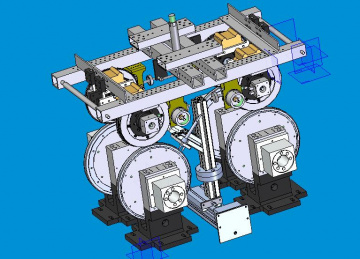
Figure 2: Roller-rig model. (Design assembly of bogie on roller Rig)
- High-speed freight boogie (scale 1:5): the prototype was realized as part of the contract "Feasibility project for a new QRRS high-speed freight bogie: dynamic analysis to support design". The scaled model of the bogie was used to perform dynamic tests on the roller-rig test bench, as shown in Figure 3, in order to evaluate the dynamic performance of the vehicle during the design activity. The prototype made it possible to optimize the choice of suspension elements and the geometry of the bogie.
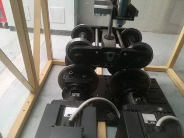
Figure 3: freight bogie prototype (scale 1:5) mounted on roller rig
- Axle-box test bench: the test bench (figure 4) allows vibrational analysis on bearings for rail use in 1: 1 scale. The device was developed as part of the NPTC project in order to evaluate the diagnostic algorithms.
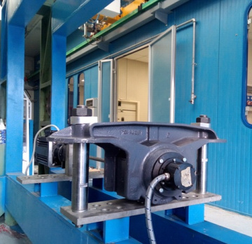
Figure 4: Axle box test bench with instrumented cap.
- Multi-axle test bench (1:5 scale): the test bench, built as part of the NPTC project, is an evolution of the roller-rig and allows simulating the passage of 4 railway wheelset, which represent the number of axles of a typical railway vehicle, on the same pair of rollers. The test bench, shown in figure 5, is composed by four wheelsets that are suspended on the same pair of rollers and are connected to a main frame by means of elastic elements. Each axle has an independent braking system. The multi-axle test bench allows two types of tests to be carried out:
- Simulation of the adhesion recovery phenomenon generated by the "cleaning" effect due to the frictional forces of the first axle that come into contact with a contaminated area of the track
- Experimental testing of anti-skid systems (WSP) of railway vehicles. These systems, based on the signals measured on the entire vehicle (typically 4 axles), cannot be tested on the roller-rig where single axle or the two axles of a bogie are typically mounted.
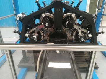
Figure 5: Multi-axle test bench.
- Seat test bench (vibrating table): the system was developed as part of the CARITAS project with the aim of assessing the effect of the seat on the comfort level perceived by the passenger. The test bench has 4 degrees of freedom (longitudinal, lateral and vertical displacement and rolling rotation) and allows real-time reproduction of the accelerations of the vehicle body. As can be seen in Figure 9, the device essentially consists of three overlapping frames, which have a degree of freedom of translation with respect to each other. The lower frame can translate vertically and rotate around the roll axis; the intermediate frame can translate with respect to the lower one along the lateral direction, while the upper frame can translate in a longitudinal direction with respect to the intermediate one. The use of this test bench is not limited to experimental tests of comfort as it can be used to perform vibration tests on mechanical components in the frequency range 0-20 Hz.
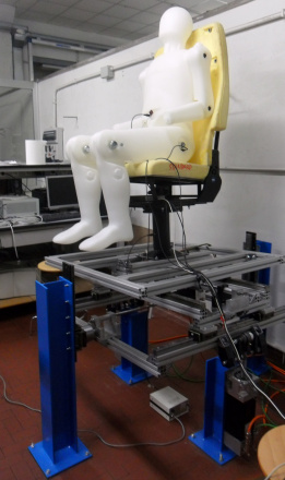
Figure 6: Seat test bench (vibrating table).
- Monitoring system for railway vehicles: the research group has been involved, since many years, in the development of monitoring and diagnostic systems for railway vehicles with the aim of increasing reliability and safety. The research activity has led to the development of different types of monitoring systems, both for freight and passenger vehicles. The system consist of a network of sensors installed on the vehicle and a central unit, see figure 7, which performs diagnostic algorithms using data received from the sensors. In particular, versions of both wired and wireless monitoring systems have been implemented. Recently, as part of the NPTC project, a monitoring system for railway vehicles has been set up that allows real-time detection of dangerous driving conditions and anomalies of the main parts of the bogie. The innovative aspect of this system is the possibility of adaptation to different types of vehicle, both freight and passengers without requiring structural changes to the vehicle. All the sensors have been included in special axle-box covers that replace the originals, see figure 8. The monitoring system includes an axial power generator completely integrated in the axle-box cap that allows powering the monitoring system when it is installed on vehicles without electrification (freight vehicles). The monitoring system has been installed on Hupac company freight vehicles, (see Figure 9 (a)), and was tested on the Velim test circuit, see Figure 9 (b).
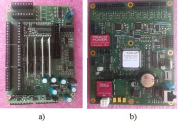
Figure 7: Monitoring central unit multiplexer system (a)
ARM microprocessor (b).
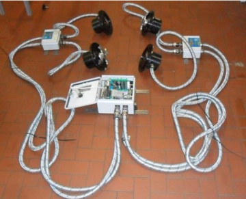
Figure 8: Monitoring system with central unit and instrumented caps.
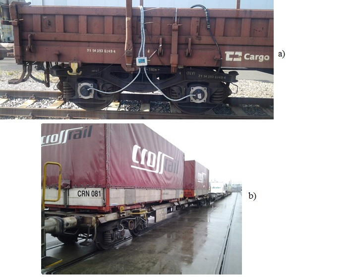
Figure 9: Monitoring system installed on a Hupac freight vehicle during tests on the Gotthard Base tunnel (a), and on the test vehicle on the Velim test track (b).